There is a gap between what a mechanical or civil engineering degree teaches about structural mechanics and what offshore structural engineering practice actually requires. It is not a gap in intelligence or effort. It is a gap in specific, code-anchored knowledge that nobody bothered to write down in a usable sequence — until recently.
These five topics are where the gap manifests most consistently. They are drawn from the first week of a 10-week offshore structural engineering programme. If you recognise more than one of them, you are not alone. That recognition is the first step.
1. Section Tables Are Not Intuitive — a UB Is Not Just an I-Beam
Choosing the right section from a standard catalogue sounds like a lookup task. In practice, it requires understanding the classification system that sits behind every section table.
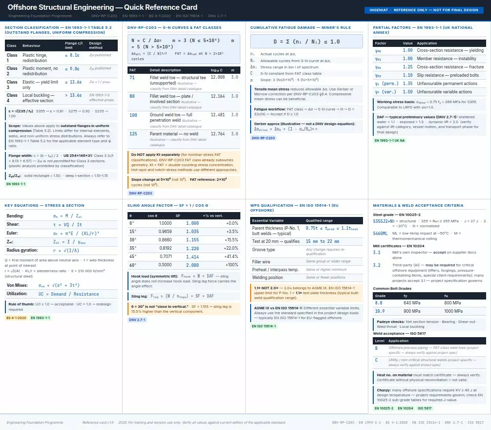
When you open BS 4-1:2020 and look for a “UB 305×165×54,” you are looking at a section with a specific nominal depth (307.0 mm), flange width (165.3 mm), flange thickness (13.7 mm), web thickness (6.7 mm), and root radius (15.2 mm). These dimensions are not arbitrary. They determine the section’s class — Class 1, 2, 3, or 4 — which determines whether you can use plastic design, elastic design, or whether you have to use effective section properties because the flange or web is locally slender.
Most graduates can calculate the second moment of area I for a rectangle. Fewer can look at a UB section table and immediately know: this section is Class 3, which means Z_pl is not published, which means I cannot use plastic design for this member, which means the utilisation ratio is calculated with Z_el = 312 cm³, not 361 cm³.
The correct Z_el for a UB 254×146×31 is 312 cm³. The wrong value — 361 cm³ — appears in some older references and in some examination papers that have not been updated since the current edition of BS 4-1 was issued. Using the wrong value produces wrong utilisation ratios. In a real design review, this would be caught. In a viva voce exam, it is the moment the examiner asks you to go back to the section tables.
2. Bending Stress Is Simple; Section Selection Is Not
The bending stress equation σ = M/Z is one of the first things taught in structural mechanics. σ = My/I, moment divided by section modulus, units of stress. The calculation is not the hard part.
The hard part is knowing which Z to use, what the partial factor γM0 means in practice, whether the section class permits plastic redistribution, and whether the deflection limit is governing over the strength check. A UB section in S355 under bending might pass the strength check (σ_b < 0.75 fy) and fail the deflection check (Δ > L/250) — in which case the section is governed by stiffness, not strength, and a deeper, more rigid section is required even though the current section is structurally adequate.
Most university courses test the calculation. Very few test the decision-making process — the part where you have to decide which limit state actually governs and why.
3. Shear Stress Is Almost Never V/A
The simplified shear stress formula τ = V/A (force divided by web area) is a convenient approximation for a rectangular section. For an I-section, it is frequently wrong — and it is most wrong when the web is thinnest and the shear is highest.
The accurate shear stress distribution in an I-section is τ = VQ/It, where Q is the first moment of area of the portion of the section above (or below) the point where the stress is being calculated, I is the second moment of area, and t is the web thickness at that point. This formula produces a stress distribution that is highest at the neutral axis (where Q is maximum) and drops to zero at the extreme fibres (where Q = 0). The simplified formula V/A — treating shear as uniformly distributed across the web — gets the location of maximum stress wrong and can significantly under- or over-estimate the peak shear stress depending on the section geometry.
In offshore practice, when a web is thin relative to its depth — as in many hot-rolled sections used in jacket platforms — the difference between V/A and VQ/It matters. The engineer who reaches for V/A without thinking about the actual stress distribution is the engineer who gets caught out when the shear check comes back borderline and the reviewer asks for the accurate value
Request our complimentary Structural Engineering Reference Card
4. Connections Govern Design, Not Members
University courses spend the majority of their time on member design: beam bending, column compression, combined loading. In real offshore structures — and in examination questions set by practising engineers, not academics — the design problem is almost always a connection.
A simply supported beam can be designed reliably using elastic theory. But a beam-to-column connection is a different problem. The bracket geometry creates stress concentrations at the weld toe. The weld toe is where fatigue cracks initiate. The crack grows under cyclic loading until the remaining cross-section fails in tension. This is not a member design problem. It is a connection design problem.
The DNV-RP-C203 FAT class system exists because of this. The FAT class is not assigned to members. It is assigned to detail categories — specific geometries of welded connections that are known from test data to have predictable fatigue performance. FAT 71, FAT 80, FAT 100, FAT 125: these numbers apply to weld toe geometries, not to steel grades. S355 and S690 steel have the same FAT class for the same joint detail. Higher-strength steel does not automatically give you better fatigue resistance. The weld geometry is what matters.
This is the piece that most graduate engineers have not been taught. It is why the Week 2 content on fatigue and failure modes — the detailed treatment of S-N curves, FAT class selection, cumulative damage using Miner’s rule, and brittle fracture — is the most practically important week of the programme.
5. Self-Weight Is Always There
Engineers who omit self-weight from their beam calculations will fail their first structural review.
This sounds trivial. It trips people up constantly, particularly in examination conditions where the problem statement gives a concentrated load or a UDL and the candidate calculates the response to that applied load without checking whether the self-weight of the member itself changes the result materially.
For a 5-metre span UB 305×165×54 in S355, the self-weight is approximately 0.54 kN/m. For a primary beam carrying 180 kN at mid-span, the self-weight is a 1.5% correction to the bending moment. Negligible in that case. But for a long-span, lightweight secondary member, or for a member in combined bending and compression where self-weight adds to the axial load, the correction is not always negligible — and the engineer who has not developed the habit of checking will sometimes forget to check.
The second-order effect: self-weight generates initial curvature and initial deflection, which interacts with compressive axial load to produce additional moments (the P-Δ effect). In a slender compression member, this interaction can be the governing design condition. The engineer who did not include self-weight in the first place cannot possibly have captured the P-Δ effect correctly.
What This List Is Actually About
These five topics are not obscure edge cases. They are the baseline knowledge gap that a 10-week offshore structural programme is built to close. Week 1 addresses all five in sequence: section selection from BS 4-1, elastic and plastic design and when each applies, the correct shear stress formula and when to use it, section classification, and self-weight in the calculation of design actions.
If you recognised two or three of these, the programme is designed for someone like you.
Our Engineering Foundation Programme covers all 10 weeks of offshore structural engineering fundamentals — from structural steel design to fatigue, materials, welding, bolted connections, lifting and rigging, pressure systems, NDT, certification, and a full capstone project. Week 1 is the foundation everything else is built on.
[See this link for more information→] Offshore and Mechanical Engineering Training Programme
Find out more, fill in your contact details below and we will come back to you as soon as possible.