How to Perform Finite Element Analysis (Step-by-Step Guide)
Performing FEA involves several key steps, each of which is critical to obtaining accurate and reliable results. The first step is defining the problem and setting up the model. This involves creating a geometric model of the structure, defining the material properties, and specifying the loads and boundary conditions. The accuracy of the model is crucial, as any errors or omissions at this stage can lead to incorrect results.
The next step is meshing and element selection. The mesh is the discretized representation of the structure, and the type and density of the mesh can significantly impact the accuracy of the analysis. Engineers must choose the appropriate element type, such as linear or quadratic elements, and ensure that the mesh is sufficiently refined in areas of interest, such as regions with high stress gradients.
Once the mesh is generated, the next step is applying loads and boundary conditions. Loads represent the external forces acting on the structure, such as pressure, gravity, or thermal loads. Boundary conditions define the constraints on the structure, such as fixed supports or prescribed displacements. It is important to apply these conditions accurately to ensure that the model represents the real-world scenario.
The solving phase involves running the FEA software to solve the system of equations and determine the response of the structure. This step can be computationally intensive, especially for large and complex models. The solver calculates the displacements, stresses, strains, and other parameters at each node in the mesh.
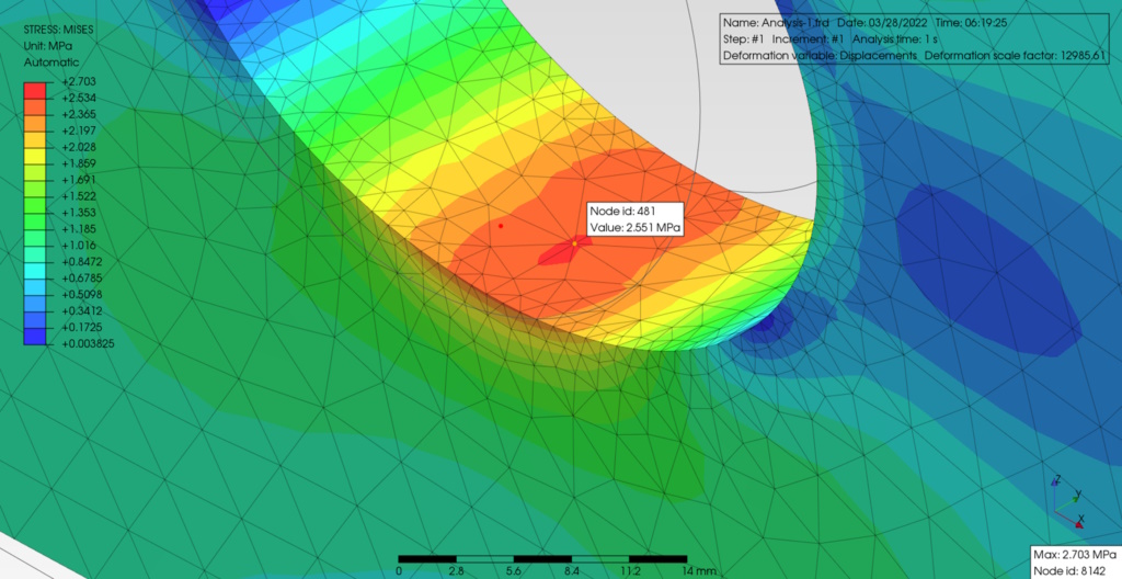
After the solver completes the analysis, the next step is postprocessing, where the results are interpreted and visualized. Engineers can generate plots, contour maps, and animations to visualize the stress distribution, deformation, and other parameters. Postprocessing is critical for understanding the behavior of the structure and identifying potential issues.
The final step is model validation and error checking. This involves comparing the FEA results with experimental data or analytical solutions to ensure that the model is accurate. Engineers must also check for errors, such as mesh distortion, convergence issues, or unrealistic results. Validation and error checking are essential for ensuring the reliability of the analysis.
Best Practices for Finite Element Analysis
Creating an effective mesh is one of the most important aspects of FEA. A well-constructed mesh ensures that the results are accurate and reliable. Structured meshes, which consist of regular, uniform elements, are often easier to generate and can provide accurate results for simple geometries. Unstructured meshes, which consist of irregular, non-uniform elements, are more flexible and can handle complex geometries. However, unstructured meshes can be more challenging to generate and may require more computational resources.
Understanding convergence and accuracy in FEA results is also critical. Convergence refers to the process of refining the mesh until the results no longer change significantly with further refinement. Engineers must ensure that the mesh is sufficiently refined to achieve convergence, as an under-refined mesh can lead to inaccurate results. However, over-refining the mesh can increase computational costs without providing significant improvements in accuracy.
Common mistakes in FEA include using inappropriate element types, applying incorrect loads or boundary conditions, and neglecting to validate the model. Engineers must carefully select the appropriate element type for the analysis, such as shell elements for thin structures or solid elements for thick structures. It is also important to apply loads and boundary conditions accurately, as errors in these inputs can lead to incorrect results. Finally, model validation is essential for ensuring that the FEA results are reliable and representative of the real-world behavior.
Interpreting stress-strain results correctly is another important aspect of FEA. Engineers must understand the difference between different types of stress, such as von Mises stress, principal stress, and shear stress, and how they relate to material failure. It is also important to consider the effects of stress concentrations, which can occur at sharp corners, holes, or other geometric features. Stress concentrations can lead to localized failure, even if the overall stress levels are within acceptable limits.
Challenges and Limitations of FEA
Despite its many advantages, FEA has several challenges and limitations. One of the primary challenges is the computational cost associated with FEA. Large and complex models can require significant computational resources, including high-performance computing (HPC) systems. The cost of software licensing can also be a barrier, especially for small companies or individual engineers.
Another challenge is the assumptions and approximations inherent in FEA modeling. FEA relies on simplifying assumptions, such as linear material behavior or small deformations, which may not always be accurate. Engineers must be aware of these assumptions and understand their impact on the results. In some cases, more advanced techniques, such as nonlinear analysis or large deformation analysis, may be required to accurately predict the behavior of the structure.
Handling nonlinear and large deformation problems is another challenge in FEA. Nonlinear analysis is more complex and computationally intensive than linear analysis, as it requires iterative solvers and more sophisticated material models. Large deformation problems, where the geometry of the structure changes significantly under load, can also be challenging to model accurately. Engineers must carefully consider the appropriate analysis type and ensure that the model is capable of capturing the nonlinear behavior.
Future Trends in Finite Element Analysis
The future of FEA is shaped by emerging technologies and trends, such as artificial intelligence (AI) and machine learning. AI and machine learning are being integrated into FEA software to automate tasks, such as mesh generation, model validation, and result interpretation. These technologies can also be used to optimize designs, reducing the need for manual iteration and improving the efficiency of the design process.
Cloud-based FEA and high-performance computing (HPC) are also transforming the field of FEA. Cloud-based FEA allows engineers to access powerful computational resources on demand, without the need for expensive hardware. HPC systems, which use parallel processing to solve complex problems, are becoming more accessible and affordable, enabling engineers to perform large-scale simulations with greater speed and accuracy.
Multiphysics simulations, which combine FEA with other simulation techniques, such as CFD and electromagnetics, are another important trend in FEA. Multiphysics simulations allow engineers to study the interaction between different physical phenomena, such as fluid-structure interaction, thermal-structural analysis, and electromagnetic-thermal analysis. These simulations are essential for optimizing designs in industries such as aerospace, automotive, and electronics.
FAQs About Finite Element Analysis
- What is the purpose of finite element analysis?
The purpose of FEA is to predict how structures and materials will respond to various physical conditions, such as forces, heat, and vibrations. FEA helps engineers optimize designs, reduce material usage, and improve product performance without the need for costly physical prototypes.
- What is the difference between FEA and CFD?
FEA focuses on structural behavior, such as stress and deformation, while CFD focuses on fluid flow and heat transfer. FEA is used to analyze the behavior of solid structures, while CFD is used to study the behavior of fluids, such as air, water, and gases.
- What is the best software for finite element analysis?
The best software for FEA depends on the specific needs of the project. ANSYS, Abaqus, SolidWorks Simulation, COMSOL Multiphysics, and Autodesk Inventor Nastran are some of the leading FEA software packages, each with its own strengths and capabilities.
- How do I learn finite element analysis as a beginner?
Learning FEA as a beginner involves understanding the basic principles of the finite element method, gaining proficiency in FEA software, and practicing with real-world problems. Many universities and online platforms offer courses and tutorials on FEA, and hands-on experience with FEA software is essential for developing practical skills.
- What are common errors in FEA and how can they be fixed?
Common errors in FEA include using inappropriate element types, applying incorrect loads or boundary conditions, and neglecting to validate the model. These errors can be fixed by carefully selecting the appropriate element type, accurately applying loads and boundary conditions, and validating the model with experimental data or analytical solutions.
- Can FEA predict material failure?
FEA can predict material failure by analyzing stress and strain distributions within a structure. Engineers can use FEA to identify areas of high stress or strain that may lead to failure and optimize the design to prevent failure. However, FEA results must be interpreted carefully, as they rely on assumptions and approximations that may not always be accurate.
- What are the advantages of using FEA in product design?
The advantages of using FEA in product design include the ability to optimize designs, reduce material usage, and improve product performance without the need for costly physical prototypes. FEA also helps identify potential issues early in the design process, reducing the risk of failure and ensuring compliance with safety standards.
Conclusion
Finite Element Analysis is a powerful tool that has revolutionized the field of engineering. By enabling engineers to simulate and analyze the behavior of structures and materials under various conditions, FEA has become an essential part of the design process. From stress analysis and thermal management to dynamic and nonlinear analysis, FEA provides valuable insights that help engineers optimize designs, reduce costs, and improve performance.
The importance of FEA in engineering and design cannot be overstated. It allows engineers to explore a wide range of design options, identify potential issues, and make informed decisions without the need for physical prototypes. As the field of FEA continues to evolve, with advancements in AI, cloud computing, and multiphysics simulations, the capabilities of FEA will only continue to grow.
Choosing the right FEA software is critical for achieving accurate and reliable results. Engineers must consider the specific needs of their projects, the capabilities of the software, and the level of support and training available. By following best practices, such as creating an effective mesh, understanding convergence and accuracy, and validating the model, engineers can ensure that their FEA results are reliable and representative of the real-world behavior.
In conclusion, FEA is an indispensable tool for modern engineering, providing the insights and capabilities needed to design safe, efficient, and innovative products. As the field continues to advance, FEA will remain at the forefront of engineering design and analysis, helping engineers tackle the complex challenges of the future.