Every offshore container that moves on an offshore installation or vessel must survive three distinct mechanical environments — each one governed by a specific load case in DNVGL-ST-E271. Get any one of them wrong and the certification fails, or worse: the container fails in service.
This post walks through all three load cases — Lifting (LC-1), Stacking (LC-2), and Floor (LC-3) — with the actual formulas, the numbers behind them, and the places where engineers most often make mistakes.
The Governing Philosophy
DNVGL-ST-E271 is a limit state design standard. The structure must remain within acceptable stress limits under prescribed design loads. The design loads are not the actual working loads — they are amplified by partial safety factors to account for uncertainty in loading, dynamics, and material properties.
The rated gross mass (Rg) is the foundation of all three load cases:
Rg = (tare mass + maximum payload) × g
Everything above Rg in the load cases is a safety amplification.
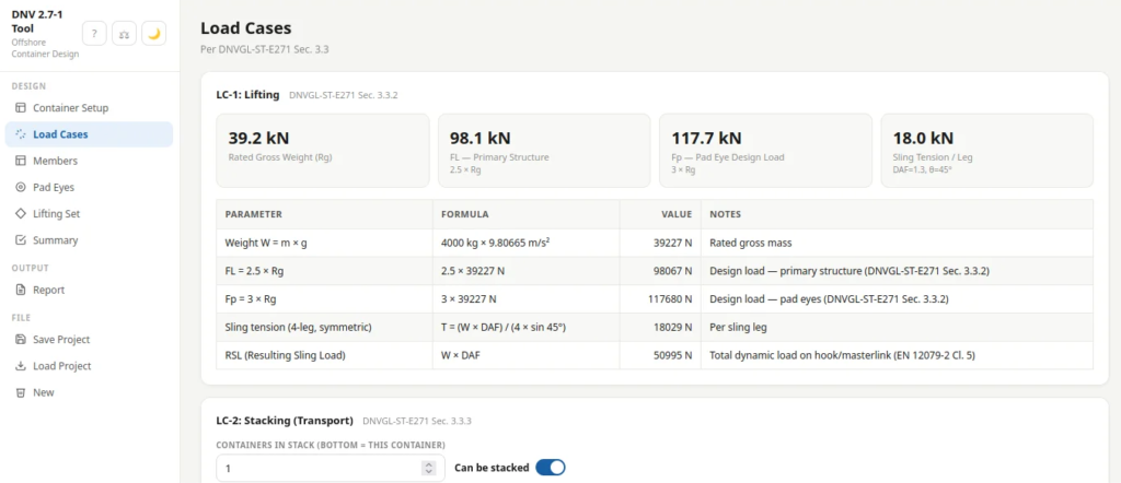
LC-1: Lifting
This is the load case that most engineers start with, and the one that drives most of the structural design. Two separate load levels apply within LC-1:
Primary Structure: FL = 2.5 × Rg
The primary structure — corner posts, top and bottom rails, side panels — is designed for a load equal to 2.5 times the rated gross weight. This covers the inertial forces from vertical lift plus the dynamic amplification from vessel motion.
The Dynamic Amplification Factor (DAF) is applied on top of the 2.5 factor. The standard does not specify a fixed DAF; it requires the designer to select one appropriate to the lifting operation. DNV-RP-E301 provides guidance: typical values range from 1.05 (controlled lift, offshore crane) to 1.3 (standard offshore lift) to 1.5 or higher (dynamic tender-drawn lifts).
FL = 2.5 × Rg (static equivalent)
T_leg = (Rg × DAF) / (n_legs × sin(θ))
Where θ is the sling angle from vertical.
Pad Eyes and Local Attachments: Fp = 3.0 × Rg
The pad eyes — the local steel structures through which the slings attach — are designed for 3.0 times Rg. This higher factor accounts for local stress concentrations and the fact that the load path into the pad eye is more complex and sensitive to fabrication quality than the primary frame.
Three failure modes must be checked for each pad eye:
Tear-out (shear rupture):
σ_tear = Fp / (t × (e − d/2)) ≤ σ_allowable
Bearing stress:
σ_bearing = Fp / (d × t) ≤ σ_allowable
Shear in bracket:
τ = Fp / (2 × A_bracket) ≤ τ_allowable
Where t = plate thickness, e = edge distance from hole center to plate edge, d = hole diameter.
All three must pass. The governing criterion is typically tear-out on thin plates with modest edge distances.
Sling Angle Constraint
DNVGL-ST-E271 caps the sling angle at 45° from vertical. A sling angle above 45° requires special justification and a revised dynamic assessment. Most certification bodies will flag this and require a higher DAF or a redesign of the lifting arrangement.
Common Mistakes in LC-1
- Using 2.5 × Rg for pad eyes instead of 3.0 × Rg — this is the most frequent error in calculation reports submitted for review
- Forgetting the DAF — the 2.5 factor is a quasi-static equivalent, not the total design load; DAF must be applied separately
- Mismatching sling tension direction — sling angles must be resolved to vertical components correctly; asymmetric lifts require full equilibrium analysis
- Assuming 4-point symmetric lift is always valid — if the container is not symmetric or if the lift points are not evenly loaded, a 2-point or asymmetric analysis is required
LC-2: Stacking
During transport, offshore containers are frequently stacked in vessel holds or on deck. LC-2 covers the bottom container in a stack and accounts for the accelerations that occur during sea transport.
The Stacking Load: Fs = 2.0 × Rg
The bottom container in a stack must sustain 2.0 × Rg — this is the design stacking load per container. A stack of three containers means the bottom container is subject to the weight of the two containers above, multiplied by a dynamic amplification factor implicit in the 2.0 factor.
The standard specifies this load as a uniformly distributed compressive load applied at the corner fittings (ISO 1161 interface points). The load path goes through the corner posts and bottom rails.
The "Not to be Stacked" Marking
Containers that cannot sustain stacking loads — either because of structural limitations or because of their contents — must be marked with the "NOT TO BE STACKED" notation under DNVGL-ST-E271. Marking a container as non-stackable when it actually is stackable is a commercial restriction; marking it as stackable when it is not is a safety failure.
Common Mistakes in LC-2
- Not checking the stacking capability of the specific container profile — a 6ft cargo basket has different stacking performance than a 20ft reefer
- Omitting the stacking check when the container is certified for stacking — engineers often skip LC-2 when they think the container "won't stack in practice"; certification is about the design capability, not the planned use
- Confusing LC-2 with LC-1 — they use different load factors (2.0 vs 2.5 for primary structure) and different load application points
LC-3: Floor Load Case
LC-3 covers the base structure of the container — the floor plate, stiffeners, and base rails — under both uniform floor loading and concentrated loads from forklift pockets.
Uniform Floor Load
DNVGL-ST-E271 Table 4-1 (referenced) gives minimum floor plate thicknesses based on stiffener spacing. The design floor load is typically specified by the customer or derived from the intended cargo — a container carrying heavy machinery may have a floor load requirement of 20–25 kN/m², while a standard cargo basket may only need 10 kN/m².
The floor plate is designed as a simply supported plate on an elastic foundation (the stiffeners below). The stiffeners carry the floor load to the bottom rails.
Forklift Pocket Check
If the container has forklift pockets, LC-3 must include a concentrated load check simulating a forklift axle. The standard approach is to apply a point load of 2 × the maximum wheel load at the most critical location in the pocket.
Common Mistakes in LC-3
- Using the wrong floor load value — always verify with the customer or the intended cargo; under-specifying floor load is a common reason containers fail when loaded with heavy equipment
- Ignoring forklift pocket dynamics — the pocket is a stress concentration; the check must be local, not global
- Forgetting to check the stiffeners supporting the floor — the floor plate is only as strong as the stiffener system below it
Load Case Interaction
In practice, a container in service may experience combined load cases — for example, a container that is lifted while already stacked internally (e.g., a waste skip with a lid). DNVGL-ST-E271 does not require a formal combination of LC-1, LC-2, and LC-3 in the same way that structural codes require combinations of live and dead loads in building design. However, a well-engineered container should be assessed for the most critical condition in each respect, and the envelope of all three load cases should be considered.
The summary section of your certification report should show clearly which members pass which load case, and which is the governing case for each member.
The Bottom Line
All three load cases are required. They are independent checks, not alternatives to each other. The structure must pass all three — there is no "majority wins" provision.
| Load Case | Load on Primary Structure | Load on Pad Eyes |
|---|---|---|
| LC-1 Lifting | 2.5 × Rg | 3.0 × Rg |
| LC-2 Stacking | 2.0 × Rg per container | N/A |
| LC-3 Floor | Per customer spec (kN/m²) | Forklift axle × 2 |
The calculations are straightforward. The errors come from wrong load factors, missed DAFs, and confusion about which case governs which part of the structure.
Calculate all three load cases with full DNVGL-ST-E271 clause traceability using the DNV 2.7-1 Offshore Container Design Tool — generates certification-ready PDF reports in minutes, not hours.
Find out more, fill in your contact details below and we will come back to you as soon as possible.