A low grade marine Waste Heat Recovery Unit is a system designed to capture and convert low-grade waste heat from ship engines into usable electrical power. It uses an organic working fluid with a lower boiling point than water, allowing it to operate efficiently at lower temperatures compared to traditional steam cycles.
As they typically follow the Rankine cycle using organic fluids, they are often referred to as Organic Rankine Cycle (ORC) units.

IMO’s strategy for reducing greenhouse gas emissions from shipping — targeting net-zero GHG emissions by or around 2050 — places energy efficiency improvement at the centre of every vessel’s decarbonisation pathway. CII (Carbon Intensity Indicator) ratings and EEXI (Energy Efficiency Existing Ship Index) compliance have elevated the commercial and regulatory value of any technology that reduces fuel consumption without modifying the prime mover itself. The Organic Rankine Cycle (ORC) waste heat recovery system is one of the most technically mature of these technologies, converting otherwise-lost thermal energy from a ship’s main engine and auxiliary systems directly into useful electricity.
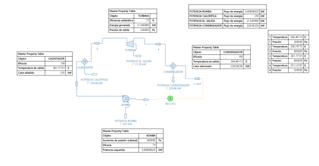
Unlike steam Rankine systems — which require high-grade exhaust heat above 300 °C and are economically viable only on very large vessels — ORC systems use organic working fluids with low boiling points, enabling efficient power generation from heat sources as low as 70–80 °C. This makes them suitable across a far wider range of vessel types: medium-speed diesel vessels, dual-fuel LNG ships, offshore platform supply vessels, and even gas turbine installations. The working fluid circulates in a closed loop — evaporating, expanding through a turbine to generate electricity, condensing, and being re-pressurised by a feed pump — returning continuously to absorb heat again.
The ORC waste heat recovery process involves the following stages:
A) Heat Source Identification and Capture:
Waste heat is extracted from available sources: exhaust gas (300–550 °C), high-temperature jacket water (~90 °C), scavenge air coolers, and auxiliary engine exhausts.
A thermal oil circuit or hot water loop typically carries energy from the heat source to the ORC evaporator, providing thermal buffering and isolating the working fluid from the flue gas stream.
B) Evaporation of the Working Fluid:
The working fluid — typically R245fa, toluene, cyclopentane, or a silicone-based fluid — is pumped as a subcooled liquid to the evaporator heat exchanger at high pressure.
Within the shell-and-tube or plate-type evaporator, it absorbs heat from the thermal oil or hot gas, passing through preheating (liquid), evaporation (two-phase), and superheating (vapour) stages.
C) Expansion and Power Generation:
The high-pressure superheated vapour is admitted to an expander — a screw, radial inflow, or axial turbine depending on the power range — where it expands to low pressure, converting enthalpy drop directly into shaft work.
Isentropic efficiency of well-designed expanders ranges from 70–85%, with hermetically sealed designs common in smaller units to eliminate shaft seal leakage of the working fluid.
D) Electrical Output:
The expander shaft drives a synchronous generator or permanent magnet generator (PMG), producing AC power at 440 V or 6.6 kV for direct connection to the vessel’s main switchboard.
A frequency converter is typically used to decouple generator speed from grid frequency, allowing variable-speed operation that optimises expander efficiency across the range of available heat.
E) Condensation and Heat Rejection:
The low-pressure exhaust vapour from the expander passes to a condenser — shell-and-tube or keel cooler type — where seawater or central cooling water absorbs the remaining heat, condensing the vapour to a subcooled liquid.
A vacuum pump or ejector system removes non-condensable gases that would otherwise accumulate and degrade condenser performance.
F) Feed Pumping and Cycle Control:
A centrifugal or gear-type feed pump, driven by a variable frequency drive, re-pressurises the condensate from condenser pressure back to evaporator pressure, completing the thermodynamic cycle.
The control system — PLC-based with SCADA integration — continuously regulates mass flow, superheating, and expander speed to maximise net power output, while monitoring safety parameters and triggering ESD on abnormal conditions.
This closed-loop thermodynamic approach converts otherwise-wasted thermal energy into useful electricity with no additional fuel consumption, no moving combustion components, and no emissions impact. It represents one of the most impactful single-technology investments available for improving a vessel’s CII rating and EEXI compliance.
The following considerations are key to understanding this technology and its potential applications:
Key Advantages:
- No additional fuel consumption — electricity generated purely from recovered waste heat
- Direct reduction in auxiliary generator running hours, reducing fuel burn and maintenance costs
- Improvement in CII rating and EEXI compliance with no operational constraints on the vessel
- Closed working fluid cycle — no emissions, no combustion, inherently low maintenance
- Suitable for low- and medium-grade heat sources unavailable to conventional steam Rankine systems
Modular, skid-mounted construction supports retrofit and newbuild installation equally
Regulatory Considerations (IMO / CII / EEXI):
- IMO’s MEPC 80 confirmed the trajectory toward net-zero GHG by 2050, maintaining commercial pressure on CII improvement year-on-year from 2023 onwards.
- ORC power output directly offsets auxiliary generator consumption, reducing SFOC-equivalent figures used in CII and EEXI calculations.
- Classification societies (DNV, BV, LR) provide type approval for ORC units; installation requires class review of integration with main engine exhaust and ship’s electrical system.
Operational Aspects:
- ORC systems operate continuously in parallel with the main engine, starting and stopping automatically with the vessel’s propulsion system.
- Net power output varies with heat source temperature and mass flow — typically following the main engine load curve, with maximum output at MCR.
- Maintenance is primarily filter changes, working fluid sampling (annually), and expander bearing inspection (per OEM schedule, typically 16 000–24 000 hours).
Challenges and Considerations:
- Working fluid selection must balance thermodynamic performance, environmental properties (low GWP), safety classification (flammability, toxicity), and regulatory compliance (F-Gas Regulation, Kigali Amendment).
- Integration with the main engine exhaust system requires careful back-pressure analysis to avoid adverse effects on turbocharger performance and engine efficiency.
- Available deck space and weight budget may constrain system sizing, particularly on retrofit projects where the baseline engine room was not designed to accommodate waste heat recovery equipment.
Future Outlook:
- Growing commercial adoption is expected as CII ratchet tightening makes fuel savings increasingly valuable — a vessel avoiding 300 tonnes of HFO per year at $600/tonne saves $180 000 annually.
- Cascade ORC systems combining high-temperature exhaust gas and low-temperature jacket water circuits are under development to maximise total heat recovery efficiency.
- Integration with battery energy storage and variable-speed propulsion systems will enable smarter energy management across the full voyage profile.
Strategic Role in Sustainable Shipping: The Organic Rankine Cycle waste heat recovery system represents one of the most technically mature and commercially proven routes to improving vessel energy efficiency, directly addressing CII and EEXI obligations while reducing operating costs — with no change to vessel operations or cargo capacity.
We can provide the following engineering services associated with the design and installation of a waste heat recovery unit.
- Feasibility Study and Concept Design:
- Evaluation of space availability and weight considerations
- Preliminary process flow diagrams
- Conceptual layout designs
- Initial cost estimates and project timeline
- Detailed Engineering Design:
- Process engineering and equipment sizing
- Piping and Instrumentation Diagrams (P&IDs)
- 3D modeling of the equipment layout
- Electrical system design and integration
- Equipment Specification and Procurement Support:
- Development of technical specifications for major equipment
- Vendor evaluation and selection assistance
- Review of vendor documentation and drawings
- Structural Modifications Design:
- Reinforcement designs for existing structures if required
- Finite Element Analysis (FEA) for critical structural components
- Integration Engineering:
- Interface design with existing ship systems (e.g., power, water)
- Modification of existing piping systems
- Safety and Risk Engineering:
- Failure Mode and Effects Analysis (FMEA)
- Regulatory Compliance and Classification:
- Liaison with classification societies
- Preparation of documentation for class approval
- Development of procedures to meet regulatory requirements
- Installation Planning:
- Development of detailed installation procedures
- Creation of work packages for shipyard or offshore installation
- Lift plans for major equipment
- Installation sequence optimization
- Commissioning and Start-up Support:
- Development of commissioning procedures
- Supervision of installation and commissioning activities
- Performance of system tests and trials
- Troubleshooting and optimization support
- Documentation and Training:
- Preparation of operating and maintenance manuals
- Development of crew training programs
- Environmental Impact Assessment:
- Analysis of the recovery unit’s environmental benefits
- Support for environmental permit applications
- Project Management:
- Overall project scheduling and coordination
- Cost control and progress reporting
- Quality assurance and control
- Lifecycle Support:
- Development of maintenance and inspection schedules
- Optimization studies for long-term operation
- Technical support for system upgrades or modifications
- Feasibility Study and Concept Design: